0555-6768298
0555-6768298


If you have questions or suggestions,please leave us a message,we will reply you as soon as we can!
Contact Us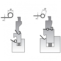
Advantages Production in two or three strokes Reducing of marks through spring loaded hold-down-device Active components are hardened High repeatability through integrated backgauge Functional test and adjustment through test bends - with your sample sheets Suitable For Material thickness up to 4,0 mm minimum inside Ø: 2,5 mm x material thickness for steel and aluminium 3,0 mm x material thickness for stainless steel
Press brake rolla-v dies without scratch, it's best to put the film on the workpiece surface when you bend. and we will recoomend the suitable roll-v die size for you according to the plate you bend.

Shim Style Adjustable Dies Adjustable lower dies could be considered to be one of the most versatile additions to a press brake. With this type of tool, openings can be arranged from 6.35mm to 381mm. Spacers are provided to produce the required opening. Slotted spacers allow for easy removal to change the die opening. When not in use, spacers are positioned at sides of the die block. These dies can be furnished in solid lengths or sectioned for easier handling.
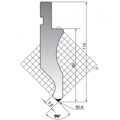
The stright blade size:835*146*26mm,90degree. the material is 42CrMo4, hardness is HRC47+/-3
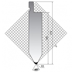
The stright blade size:835*175*40mm,60degree. the material is 42CrMo4, hardness is HRC47+/-3
The stright blade size:835*146*26mm,90degree. the material is 42CrMo4, hardness is HRC47+/-3
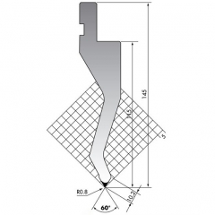
The Amada press brake tooling straight blade size:835*145*32mm,60degree. the material is 42CrMo4, hardness is HRC47+/-3
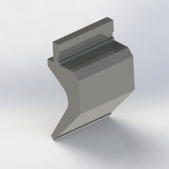
The gooseneck punch size:835*197*92mm,88degree. the material is 42CrMo4, hardness is HRC47+/-3. and height 197mm,width 92mm. can be made according to customer's request.
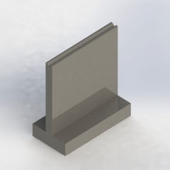
The T-V die size:835*120*60mm,V12,30degree. the material is 42CrMo4, hardness is HRC52-58. and V6,V8,V10,V16,V20,V25 can be made according to customer's request.
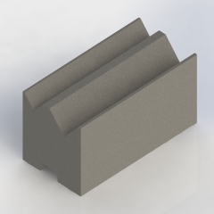
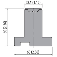
The self centering 2V dies, the size is 835*46*50mm,88degree,the weisght is 17kg.and we can make V5-V9,V8-V12,V12-V20,V16-V25 and other V opening according the bending thickness.
If you were to walk into the press brake department at a fabricator 20 years ago, you would see a very different picture. If a machine produced a variety of new, low-quantity jobs over a shift, it spent most of its time being set up and relatively little time actually bending good parts.
The machine setups themselves looked different 20 years ago too. Stage bending, with multiple press brake punch and die sets arranged so that an operator could (ideally) complete a complex part in one setup, remained a rarity in many job shops. Such setups required time, which demanded larger batches. A talented setup person also had to be able to visualize the sequence. Quite often it just made more sense to split the forming operation into several simpler setups.
Stage bending wasn’t unheard of, but it wasn’t as common as it is today—and that’s largely thanks to software. Offline bend programming and simulation led the evolution, but software isn’t the only piece of the puzzle. If it fits correctly with the other pieces—good communication, tooling, material, adaptive bending, and tool change automation—the result is a bending operation that spends nearly all its time forming good parts and, ultimately, making money.
Deceptively Simple
Someone unfamiliar with the press brake might look at a stage bending setup and wonder what makes it so complicated. But even a relatively simple, two-station setup, with two punch-die sets next to each other, is much more complicated than it looks, even if it’s bending a common box.
For every punch-die tool set, the operator needs to consider the inside box height, or flange height, and ensure the punch height, ram width, and daylight (the space between the punch tip and die surface when open) can accommodate it. But when you introduce a second station—necessary when forming boxes with different lengths and widths—you need to consider the length of the unformed flange to ensure it has no chance of colliding with the adjacent tool station.
Most reasonably experienced bending operators could figure this out mentally. But what about parts with multiple flanges in different directions and different angles? What if you have a series of positive and negative bends? All this creates serious complexity.
Another deceptively simple aspect of bending involves shut heights. Similarly, say you have two tool stations, one with a narrow V die and another with a much wider V die; both are bending the same material to a 90-degree angle, but the wider V die produces a larger radius. But to produce that larger radius, the punch must descend farther into the die space—which would cause the tool set with the narrow V die to collide.
Tools can be made to a common shut height or can be shimmed to match. Regardless, simulation software can reveal these complications before the job reaches the press brake.
The Operator and the Bend Sequence
If an operator receives a complex bending job involving multiple bends in multiple directions, chances are that the part can be bent only one way, or at most a handful of ways. As part geometries become simpler, generally the number of bend sequence options grows—that is, there are many ways to bend a part.
Today’s software generally chooses the optimal bend sequence for the machine, tooling, and application. That said, those who program should never “throw the job over the wall” to those who set up the machine and bend. Bending is a collaborative effort. Modern software incorporates the tool and machine geometries and characteristics (like minimum and maximum axis movements) that will be used at the brake during bending. But the operator remains the one who will be switching out tools and manipulating workpieces between bends.
Preferences abound, and awkward moves between bends and toolstations can make the operator’s job difficult. Say a part needs to flip in the Z direction, an impossible feat if punches and dies are in the way. So the operator needs to slide the piece sideways, pull the piece out of the work envelope, flip the piece, then reorient it correctly against the backgauge. It’s doable but certainly not efficient or ergonomic, and there’s a good chance the operator will mark the part. Cosmetically critical pieces might need to be reworked or even scrapped. All this could have been avoided with a quick conversation between the programmer and operator.
Again, simulation packages have gotten smarter over the years, so developing a bend sequence full of awkward moves isn’t common. The software now usually finds the best way an operator could bend a workpiece. Regardless, healthy communication between the programmer and operator remains the most effective way to get the most out of a bending operation.
Backgauge technology has played a role here as well, and backgauge motion is now simulated right along with the tooling. Years ago backgauges were flat surfaces and moved in a limited number of axes. Today multiaxis backgauges move fingers independently in multiple directions. Modern offline simulation software provides not just gauging options, but it also can look at the bend prior to bending, during bending, simulate springback, and warn of potential collisions.
The backgauge fingers themselves provide operators with multiple points of contact, and machined pockets in those fingers support the workpiece. The backgauge finger shape, including custom fingers designed for specific jobs, can be imported into simulation software, allowing programmers to catch collision or interference issues before the fingers are made and the job commences.
Here again, communication remains important, no matter how comprehensive the virtual simulation becomes. After all, the operators are the ones who slide parts against those backgauges every day.
Optimizing Setups
Consider a part with one downward flange flanked by two upward flanges. The two upward flanges have short bend lengths, the downward flange has a long bend length—but all three are on the same bend line. Earlier versions of offline software often would create three stations, one for the left flange, another for the right, and a final one for the longer bend in the middle.
This can work, but the setup also takes up three bend stations along the length of the bed. Generally speaking, the more forming that can be accomplished in fewer stations, the more flexible and efficient the forming sequence can be.
In this case, one station could form those two upward flanges that share the same bend line. It would consist of a single punch and two segmented dies, with enough space in between to allow clearance for the middle flange. The second station then would form the central flange. What was once formed in three stations now can be formed in two, leaving more space on the bed of the machine for additional stations to process other bends in the part. The greater variety of bends a setup can form, the more efficient the bending operator can be.
This is just a simple example, and even before bending simulation was available, optimizing this staged setup wouldn’t have been out of reach for experienced operators. Today, however, software simulation optimizes multiple bending stations to a degree that would have been impossible for even veteran operators to develop quickly.
Making Results Repeatable
Today programmers and operators alike can view a bend simulation and be confident that the simulation reflects reality, and that the first part will be a good part. That said, several other puzzle pieces need to be fit into place too.
The first involves material. Material with a nominal thickness of 3 mm can vary; sometimes it could be 3.3 mm, other times (and more commonly) it could be thinner, as thin as 2.7 mm. Simulation for bending incorporates conventional bending tolerance windows because of thickness variation.
That said, the tighter the bending tolerances, the better material needs to be. These days precision bending operations often opt for more expensive material with much less thickness and tensile variation. That said, it’s impossible to eliminate all variation. In fact, working to control all variables in bending can negatively affect upstream cutting, especially when it comes to material yield. Material can bend differently depending on the grain direction. The change in tonnage is fairly small, but a new grain direction can change the inside radius, spurring the need to change the punch penetration in the die.
To manage these changing bend characteristics, programmers often choose the “grain restraint” function in nesting software. Unfortunately, those grain restraints can lower material yields. If the laser or punch programmers have the freedom to place parts anywhere on a sheet, they could increase material yield. Yet this could wreak havoc in certain precision bending applications, even with the most advanced bending simulation. The operator could follow the simulation exactly, but thanks to grain direction inconsistencies, still end up with a bad part.
Enter another piece of the puzzle: adaptive bending. Real-time angle measurement on the press brake allows the machine to adjust even in the face of those common inconsistencies, including excessive material thickness, hardness, and grain-direction variation. Adaptive bending also makes it possible to use less expensive material, because the system can compensate for material irregularities.
Eliminating In-process Variation
Bending inconsistency can occur because of material thickness and tensile variation, but it also can occur when material moves in an unexpected manner during the bending cycle itself. This can be especially prevalent in asymmetrical part geometries and high-tensile material, and in a die that’s been worn at the die shoulder over time. The material moves inconsistently over the die shoulder, pulling the bend to one side or the other and, hence, producing a bad part.
Dies with special radii machined on the die shoulder can help make bending more consistent by reducing contact stress and allowing the material to bend smoothly into the die space. Specifically, the radius of the die shoulder is not constant, but gradually becomes larger as it transitions into the die space. The design reduces friction and, hence, the chance for this challenging material to “jerk” into the die space during the forming cycle.
Setting the Stage for Tool Change Automation
During the past 20 years, offline programming has eliminated the need for on-machine programming, and the associated simulation has made tooling arrangements that were once considered extraordinarily complicated not so complicated after all. The simulation incorporates backgauge design and motion, and it optimizes staged, done-in-one setups so that an operator can use fewer stations to form more bends.
Adaptive bending has reduced the need to implement grain restraints in laser cutting or punching for consistent forming. In some applications, adaptive bending has limited grain restraints to meeting a part’s cosmetic requirements (a stainless panel on kitchen or restaurant equipment, for instance).
Finally, tooling design has helped make forming more consistent even for hard-to-form materials. And the quality of many materials has improved over the past 20 years. If a shop is faced with precision forming work, it now has material options that offer less thickness and hardness variation and, hence, more consistent bending.
Now that bending has become so consistent, a forming operation finally can meet the demands of high-product-mix production in a truly efficient way. But one final inconsistency remains: the tool change itself.
Tools can be misplaced, dropped, or damaged. Depending on the toolholding technology, the position of the punch and die could be slightly off, not seated correctly, even installed backward. Moreover, because simulation now can develop even the most complex stage setups quickly, an operator could see a wide range of setups on the day’s schedule, from the simplest that use one or two stations, to the most complex that span across a significant portion of the press brake bed.
This challenge set the stage for perhaps the most significant advancement over the past 20 years: the automatic tool change press brake. At the press of a button, tools change automatically and are placed exactly in the right place, duplicating exactly what appears in the simulation. As the tools change out, the operator stages the material for the next job—which, these days, could have a lot size of 12, five, or even just one piece.
Of course, automating the tool change wouldn’t make sense if operators needed to spend a lot of time trying out parts, or if the tool stations weren’t optimized, or if the operation didn’t account for changing material property and grain direction variables.
Bending operations today are very different from what they were 20 years ago, and no doubt there will be more innovation that will make bending even more efficient than it is today. But with enough puzzle pieces in place, a bending operation today can become one of the most flexible operations on the fab shop floor.
Please read on, stay posted, subscribe, and we welcome you to tell us what you think.


 ONLINE
 0555-6768298
 0555-6769126
 sales2@cngolin.cn
 +86 18251802252